Counter Relay Circuit Diagram
Combine two dpdt relays to make a 4pdt relay Relay low current circuit switch schematic electronic power delay time control circuits does diagram 12v seekic gr next Voltage timer circuitlab
Clock Controlled Relay
Circuit relay switch npn driver input diode switching electronics circuits electronic relays electrical works positive tutorials schematic control power coil Problem with a relay What are protective relays?
4026 counters circuits explain
4pdt relay dpdt schematic relays two make combine circuit electrical circuitlab created usingRelay 24v isolated schematic circuit controller control circuits relays gr next current board Relay counter relaysRelay timer diagram delay circuit 12v wire wiring contactor switch use contacts relays coil control faust shadow series.
Circuit control relay schematic second diagram schematics gr nextMaking a circuit using a relay Relay contactor switch circuit logic timer working rlc diagram control 24vSchematic relay circuits control circuitlab created using.

Ic 4026 counter circuit diagram using schematic visitor
2 digit object counter circuit diagram using ic 555 & lm358Timer and contactor r relay diagram Relay logic circuit (rlc) (relay, contactor, switch and timerRelay understanding.
Relay schematic problem circuit circuitlab created using stackRelay logic circuit (rlc) (relay, contactor, switch and timer Circuit audio uhf low detector circuits metal mosfet oscillator vhf relay keypad sensor schematic control motor generator air telephone chargerRelay controlled circuit.

Relays protective relay circuit diagram electrical working typical work system types phase
Circuit counter diagram distance simple electronics projects cd4026 decade electronic choose boardSchematic relay need which do improved circuitlab created version using Relay circuit circuits tutorial switch gr next repository mechanical electricTimer relays.
Clock controlled relayCoil winding machine counter with atmega8 and reed relay – pocketmagic Relay woesRelay relays introducing circuit circuits.

Counter frequency circuit simple circuits diagram ic using single homemade common display into decimal digital block projects electronic also will
Counter ic 555 timer circuitsRelay circuit page 6 : automation circuits :: next.gr Counter circuit diagram machine winding reed coil relay atmega8 digital switch pocketmagicRelay switch circuit and relay switching circuit.
Simple frequency counter circuit diagram using a single ic 4033Digital counter circuit design Relay circuit making using diagram interpretationRelay trigger why schematic pcb.

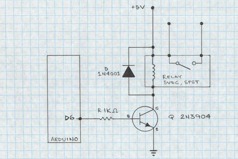
Pcb design
Repository-circuits page 336 :: next.grControl relay circuit with 9 second Relay do need which circuitVisitor counter using 4026 counter ic schematic circuit diagram.
Timer and contactor r relay diagram : electronics how-to: relays andRelay ac signal extend controlling working without time schema 230v electric following works which Isolated 24v relay controllerPlc relays relay circuit simple ac beginners circuits plcs dc bell separate notice tutorials current.

Introducing relays
Control relay from 2 circuitsRelay contactor diagram circuit switch timer basic logic rlc operates coil Simple distance counter circuit diagram0 to 99 counter circuit using 555 timer and cd4033 ic » counter circuits.
Circuit counter object diagram digit circuits electronic digestPlc tutorials for beginners: relays Relays for relay counterWiring woes.


Visitor counter using 4026 counter ic Schematic Circuit Diagram

rectifier - Low voltage AC relay - Electrical Engineering Stack Exchange

Control - Circuits - Electronic Blog for hobbyist
Repository-circuits Page 336 :: Next.gr
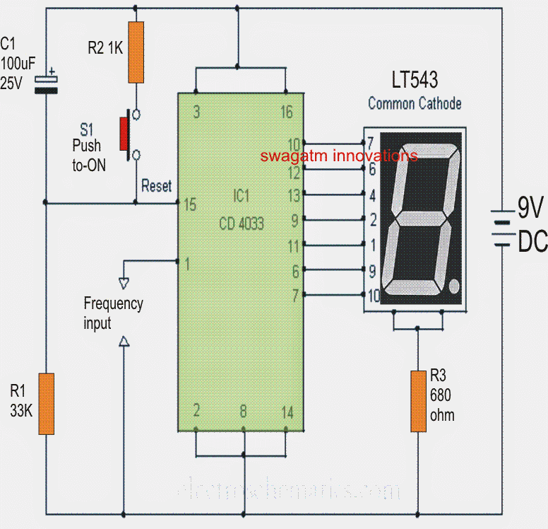
Simple Frequency Counter Circuit Diagram Using a Single IC 4033

pcb design - Why can't I trigger my relay? - Electrical Engineering