8 Bit Full Adder Circuit Diagram
8 bit adder circuit Adder bit circuit logic half make gates diagram comparator two electronics first memory questions cout difference between there only second Adder bit circuit
Block diagram of an 8-bit adder (32-bit adder is essentially the same
Adder subtractor bit make carry ripple verilog circuit binary diagram using 4bit want geeksforgeeks output hdl has source 😊 four bit parallel adder. 4 bit binary adder circuit / block diagram Let's learn computing: 4 bit adder/subtractor circuit
Full adder logic diagram
Cs 3410 spring 2018 lab 1Adder logic half boolean implementation Adder theorycircuitAdder adders libretexts circuits pageindex.
Block diagram of an 8-bit adder (32-bit adder is essentially the sameAdder bit carry logic diagram verilog look digital ahead collaborative learning hdl circuits arithmetic binary figure lookahead generator four name Logic diagram for 8 bit adderFitfab: 8 bit adder truth table.

Adder cmos soi
Vhdl tutorial – 21: designing an 8-bit, full-adder circuit using vhdlLogic gates 10+ adder circuit diagramAdder bit using circuit adders half four circuits implementation watson single just box latech edu.
Combinational and sequential design of a 4-bit adder. (a) ha circuitProposed 1-bit full adder circuit. Adder bit digital logic gates 32 adders interview division circuit using addition questions gate diagram electronics biological logisim xor javascriptAlu diagram block adder mini bit introduction figure final.

Adder logic wiring calculators
Adder circuit bit proposed6.4: 2-bit adder circuit 13+ full adder block diagram16 bit full adder digital circuit simulation using logisim software.
Adder combinational sequentialAdder alu nor nand Full adder circuit: theory, truth table & constructionFull adder circuit diagram.

Proposed 1-bit full adder circuit.
Circuit diagram of a one-bit full adder using the proposed technique inAdder bit subtractor circuit ripple carry diagram logic using project build only digital computing learn let its single indie electronics 11+ 4 bit adder circuit diagramAdder bit essentially.
Adder vhdl 8bit compile simulate verify waveform programAdder circuit construction binary circuits ibm sourav gupta Adder block ripple carryAdder truth logic half sumador gates binario inputs datasheet combination suma microcontrollerslab.

Adder logisim
Adder fitfab circuitsCd4008 4-bit full adder ic pinout, working, example and datasheet Adder bit parallel four circuit binary diagram logic subtractor digital block example geeksforgeeks detailed discussion.
.


6.4: 2-Bit Adder Circuit - Engineering LibreTexts

Watson
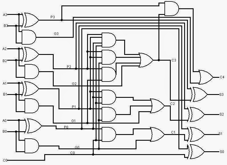
Logic Diagram For 8 Bit Adder - Wiring Diagram

Let's Learn Computing: 4 bit Adder/Subtractor Circuit
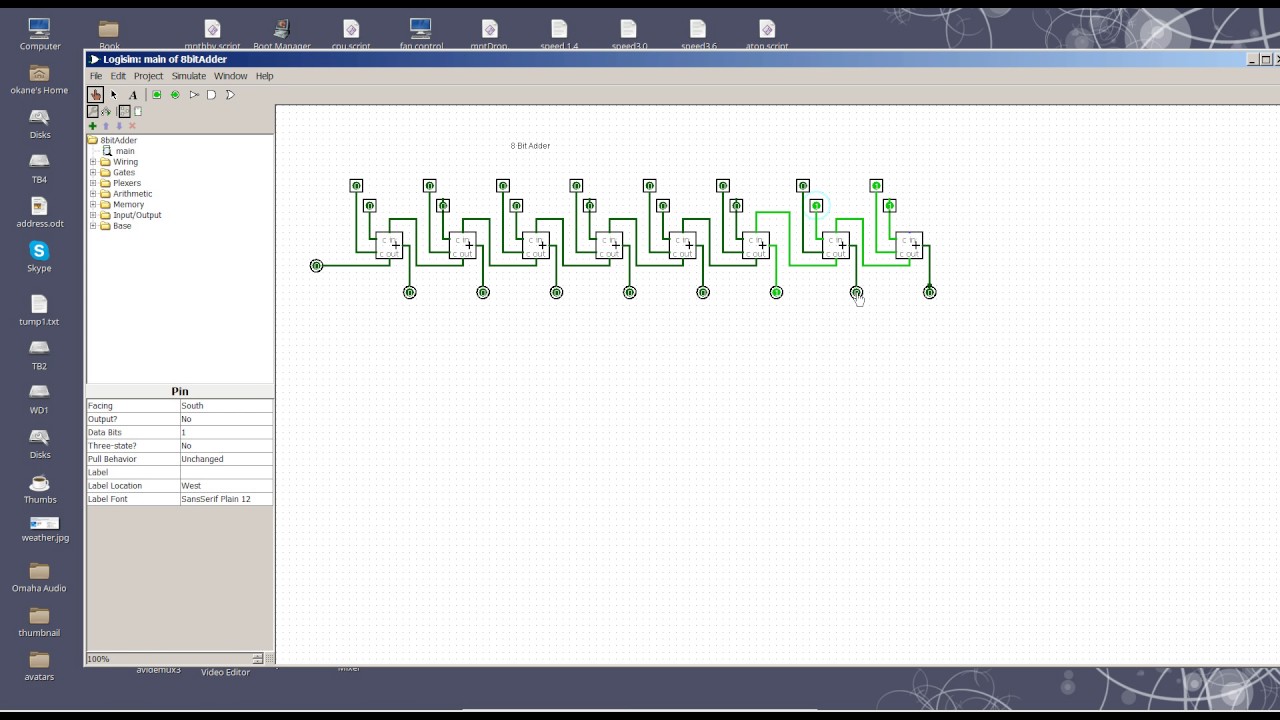
8 Bit Adder circuit - YouTube

CD4008 4-Bit Full ADDER IC pinout, working, example and datasheet

Block diagram of an 8-bit adder (32-bit adder is essentially the same