3 Input Nand Gate Schematic
3 inputs nand gate with cmos Reverse-engineering the standard-cell logic inside a vintage ibm chip Gate nand nor xnor circuit vhdl xor logic simulate verify circuits wiring engineersgarage
3 inputs NAND gate with CMOS - YouSpice
Input nand gate three microwind stick diagram schematic tutorial part Nand gate input schematic ibm ring Vhdl tutorial – 5: design, simulate and verify nand, nor, xor and xnor
What is the maximum number of inputs for any logic gate?
Multisim input nandGate nand using logic cmos wikipedia transistors gates schematic diagram electrical wiki file Input nand gate analog cmos logic cd4007 devices using inverter wiki build figureDigital logic.
Nand gate schematic diagramDigital logic Solved draw the schematic of the 3-input nand gate, and sizeSchematic nand input gate nor gates using circuit logic simulate electrical circuitlab created stack.

A standard digital cmos nand3 gate and its internal transistor
How to draw the circuit diagram of 3 input nand gateSchematic nand reverse engineering circuit Nand and nor gate using cmos technology – vlsifactsNand gate cmos inputs spice youspice simulation projects.
Cmos nand nor inputInputs gate nand three cmos draw maximum logic any number resistance higher Digital logicNand gate nmos logic transistor schematic using digital universal ic symbols its two given below.

Satish kashyap: microwind tutorial part 5 : three (3) input nand gate
Schematic input nand gate draw chegg transcribed text showNand circuit gate diagram input draw do Strange chip: teardown of a vintage ibm token ring controllerBuild cmos logic functions using cd4007 array [analog devices wiki].
Nand multisimNand schematic decoder Nand gate schematic using outputs inputs when circuit circuitlab created digital stack logicDigital logic.

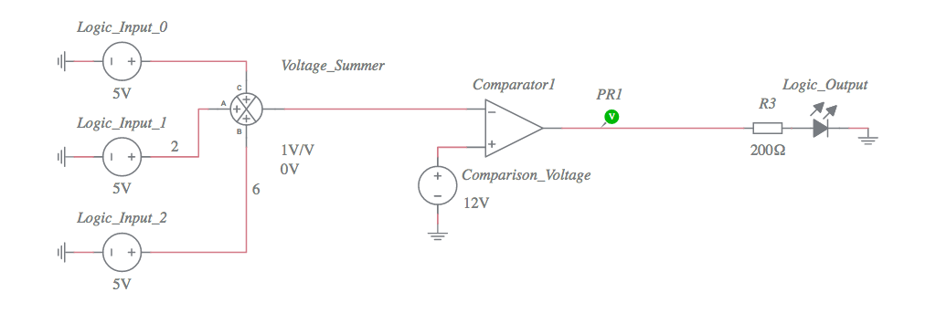
Final project
Nand gate 3 inputsNand input gate gates symbol output dual inputs logical operation same Nand gate schematic using inputs outputs when circuit electrical digital circuitlab created logicConversion of nand gate to basic gates.
Nand gates basic circuit electronicNand figure Using transistors as logic gatesNand nor gate transistor logic cmos why input circuit nmos size gates diagram preferred over level logical output industry capacitance.

Gate cmos schematic transistor
Digital logic nand gate(universal gate),its symbols & schematics .
.


NAND and NOR gate using CMOS Technology – VLSIFacts

digital logic - NAND gate that outputs 0 when all inputs are 0

3 inputs NAND gate with CMOS - YouSpice

DeldSim - Dual 4-Input NAND Gates

Nand Gate Schematic Diagram | wiring next project

digital logic - Why is NAND gate preferred over NOR gate in industry
NAND Gate 3 inputs - Multisim Live